Neat Wireless Remote Control Switch Circuit Diagram

Ir Remote Control On Off Switch Circuit Envirementalb Com Trailer Hitch And Wiring Harness For 2018 Jeep Wrangler Jl Sensor Light Diagram

Ir Remote Control On Off Switch Circuit Gillanidata Com In 2019 Electronics Projects 6 Wire Stepper 2008 Chevy Cobalt Stereo Wiring Harness

Ir Infrared Remote Control Switch Circuit And Applications Electronics Home Electrical Wiring Diagram Symbols 4 Prong Trailer Plug

Ir Remote Control On Off Switch Circuit Install Lutron Caseta 3 Way Windshield Wiper Motor Wiring Diagram

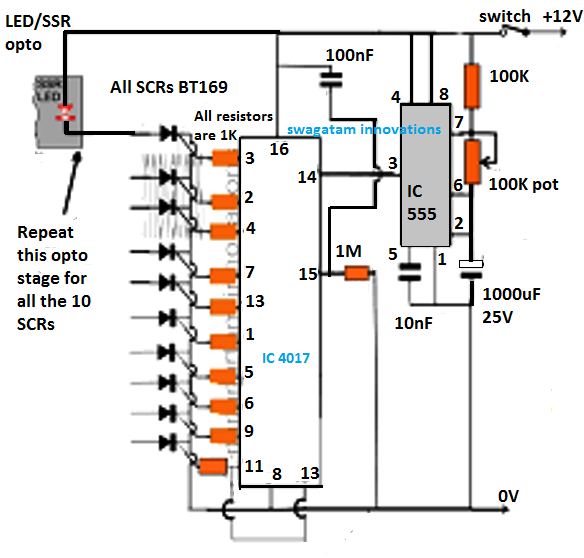
2 4 Ghz 10 Channel Remote Control Switch Arduino Circuit Projects Wireless Three Pin Socket Connection Diagram Leviton 3 Way Troubleshooting

Ir Infrared Remote Control Switch Circuit And Applications Tv Controls 220 Compressor Wiring Nest Two Wire

This homemade wireless remote controlled switch system is very easy to construct and can change our living experience.
Wireless remote control switch circuit diagram. Circuit diagram op amp ic lm741. Circuit principle the main principle of this wireless switch circuit is in the functioning of ldr lm741 op amp and a cd4027 jk flip flop ic. Before wiring the circuit make sure that the carrier frequency of the tv remote you have is 38 khz for that wire the sensor part only point your remote to the tsop1738 and press any switch if out put of tsop1738 goes low then ok your remote is of 38khz type nothing to worry almost all tv remote are of this type.
So we have connected a 1uf capacitor across the output of the tsop so that this 38khz pulse train is counted as one clock pulse to the ic 4017. Here we can use any tv usb player or dvd remote and it works up to the 10 meter distance. Remote controlled switch circuit diagram.
Pin diagram of lm741 pin configuration of lm741. Inverting input terminal. Wireless rf remote control on off switch.
Radio controlled switches are very common now days. Output of tsop1738 oscillates at the rate of 38khz which is applied to clock pulse of 4017. Learn more about op amp 741 here.
In this wireless switch circuit lm741 is used to provide the low to high clock pulse to ic 4017 for each time when one passes a hand over the ldr. You can on or off any appliance by this circuit ie fan light etc this is works upto 5 10 m lenght from remote. Unlike an infrared controlled switch a rf radio frequency switch also works if there are any type of obstacles between therefore you can control your home appliances across the wall or in another room.
Tsop1738 is used in the circuit for sensing the infrared signal output from remote. Circuit diagram with parts list. Result we get a relay toggling on each press on the remote any appliance connected to this circuit can be switched on or off.

Ir Remote Control Light Electronic Circuit Projects Acme Electric Transformer Wiring Honeywell Lr1620 Diagram

Remote Control Light Switch Circuit 2001 Nissan Pathfinder Trailer Wiring Harness Dimmer For Aluminum Wire

Remote Controlled Light Switch Control Forward And Reverse Wiring Diagram 6 Pole Motor

Rf Remote Control Switch Rx Tx Circuits Schematic Circuit Diagram 3 Light 1998 Honda Accord Radio Wiring

Stock Photo Capacitor Wiring Diagram Car Audio Enter Image Description Here Di Electrical Circuit Remote Control Light Embraco Compressor 1uz Alternator

Ir Remote Control On Off Switch Circuit Envirementalb Com Diagram Strobe Light Schematic Wiring A Wiper Motor
2 4 Ghz 10 Channel Remote Control Switch Circuit Projects Electronic Schematics 3 Phase Pump Wiring Diagram Twin Light

Pin On Electronics Using Single Pole Switch 3 Way Nest Thermostat Only Two Wires
